Usage
KiPart
KiPart is mainly intended to be used as a script:
usage: kipart [-h] [-v]
              [-r [{generic,xilinxultra,xilinx7,xilinx6s,xilinx6v,psoc5lp,stm32cube,lattice}]]
              [-s [{row,num,name}]] [--reverse]
              [--side [{left,right,top,bottom}]] [-o [file.lib]] [-f] [-b]
              [-a] [-w] [-d [LEVEL]]
              file1.[csv|zip] file2.[csv|zip] ... [file1.[csv|zip]
              file2.[csv|zip] ... ...]

Generate single & multi-unit schematic symbols for KiCad from a CSV file.

positional arguments:
  file1.[csv|zip] file2.[csv|zip] ...
                        Files for parts in CSV format or as CSV files in .zip
                        archives.

optional arguments:
  -h, --help            show this help message and exit
  -v, --version         show program's version number and exit
  -r [{generic,xilinxultra,xilinx7,xilinx6s,xilinx6v,psoc5lp,stm32cube,lattice}], --reader [{generic,xilinxultra,xilinx7,xilinx6s,xilinx6v,psoc5lp,stm32cube,lattice}]
                        Name of function for reading the CSV files.
  -s [{row,num,name}], --sort [{row,num,name}]
                        Sort the part pins by their entry order in the CSV
                        file, their pin number, or their pin name.
  --reverse             Sort pins in reverse order.
  --side [{left,right,top,bottom}]
                        Which side to place the pins by default.
  -o [file.lib], --output [file.lib]
                        Generated KiCad symbol library for parts.
  -f, --fuzzy_match     Use approximate string matching when looking-up the
                        pin type, style and orientation.
  -b, --bundle          Bundle multiple, identically-named power, ground and
                        no-connect pins each into a single schematic pin.
  -a, --append, --add   Add parts to an existing part library. Overwrite
                        existing parts only if used in conjunction with -w.
  -w, --overwrite       Allow overwriting of an existing part library.
  -d [LEVEL], --debug [LEVEL]
                        Print debugging info. (Larger LEVEL means more info.)
A generic part file is expected when the -r generic option is specified.
It contains the following items:
The part name or number stands alone on row. The following three cells on the row can contain:
- A reference prefix such as
R(defaults toUif left blank), - A footprint such as
Diodes_SMD:D_0603(defaults to blank), - A manufacturer’s part number such as
MT48LC16M16A2F4-6A:GTR(defaults to blank).
- A reference prefix such as
The next non-blank row contains the column headers. The required headers are ‘Pin’ and ‘Name’. Optional columns are ‘Unit’, ‘Side’, ‘Type’, ‘Style’, and ‘Hidden’. These can be placed in any order and in any column.
On each succeeding row, enter the pin number, name, unit identifier (if the schematic symbol will have multiple units), pin type and style. Each of these items should be entered in the column with the appropriate header.
- Pin numbers can be either numeric (e.g., ‘69’) if the part is a DIP or QFP, or they can be
alphanumeric (e.g., ‘C10’) if a BGA or CSP is used. Using a * instead of a pin number
creates a non-existent “gap” pin that can be used to visually separate the pins into groups. (This only works
when the
-s rowsorting option is selected.) - Pin names can be any combination of letters, numbers and special characters (except a comma).
- The unit identifier can be blank or any combination of letters, numbers and special characters (except a comma). A separate unit will be generated in the schematic symbol for each distinct unit identifier.
- The side column specifies the side of the symbol the pin will be placed on. The allowable values are:
- left
- right
- top
- bottom
- The type column specifies the electrical type of the pin. The allowable values are:
- input, inp, in, clk
- output, outp, out
- bidirectional, bidir, bi, inout, io, iop
- tristate, tri
- passive, pass
- unspecified, un, analog
- power_in, pwr_in, pwrin, power, pwr, ground, gnd
- power_out, pwr_out, pwrout, pwr_o
- open_collector, opencollector, open_coll, opencoll, oc
- open_emitter, openemitter, open_emit, openemit, oe
- no_connect, noconnect, no_conn, noconn, nc
- The style column specifies the graphic representation of the pin. The allowable pin styles are:
- line, <blank>
- inverted, inv, ~, #
- clock, clk, rising_clk
- inverted_clock, inv_clk, clk_b, clk_n, ~clk, #clk
- input_low, inp_low, in_lw, in_b, in_n, ~in, #in
- clock_low, clk_low, clk_lw, clk_b, clk_n, ~clk, #clk
- output_low, outp_low, out_lw, out_b, out_n, ~out, #out
- falling_edge_clock, falling_clk, fall_clk
- non_logic, nl, analog
- The hidden column specifies whether the pin is visible in Eeschema. This can be one of ‘y’, ‘yes’, ‘t’, ‘true’, or ‘1’ to make it invisible, anything else makes it visible.
- Pin numbers can be either numeric (e.g., ‘69’) if the part is a DIP or QFP, or they can be
alphanumeric (e.g., ‘C10’) if a BGA or CSP is used. Using a * instead of a pin number
creates a non-existent “gap” pin that can be used to visually separate the pins into groups. (This only works
when the
A blank row ends the list of pins for the part.
Multiple parts (each consisting of name, column header and pin rows) separated by blank lines are allowed in a single CSV file. Each part will become a separate symbol in the KiCad library.
When the option -r xilinx7 is used, the individual CSV pin files or entire .zip archives
for the Xilinx 7-Series FPGAs can be processed.
When the option -r psoc5lp is used, the CSV pin file contains the pinout text
extracted from a Cypress PSoC5LP datasheet.
When the option ‘-r stm32cube’ is used, the input CSV file should be the pin layout file exported from the STM32CubeMx tool. To create this file; create a project with STM32CubeMx then from window menu select “Pinout -> Generate CSV pinout text file”. If you select pin features or define labels for pins these will be reflected in the generated library symbol.
When the option -r lattice is used, the input CSV file should come from the
Lattice website or from their Diamond tool. (The iCE40 FPGAs are not supported
since they use a different format.)
The -s option specifies the arrangement of the pins in the schematic symbol:
-s rowplaces the pins in the order they were entered into the CSV file.-s nameplaces the pins in increasing order of their names.-s numplaces the pins in increasing order of their pin numbers and arranged in a counter-clockwise fashion around the symbol starting from the upper-left corner.
The --reverse option reverses the sort order for the pins.
Using the --side option you can set the default side for the
pins. The option from the CSV file will override the command line
option. The default choice is left.
Specifying the -f option enables fuzzy matching on the pin types, styles and sides used in the
CSV file.
So, for example, ck would match clk or rgt would match right.
Specifying the -b option will place multiple pins with the identical names at the same location
such that they can all attach to the same net with a single connection.
This is helpful for handling the multiple VCC and GND pins found on many high pin-count devices.
The -w option is used to overwrite an existing library with any new parts
from the CSV file. The old contents of the library are lost.
The -a option is used to add parts to an existing library.
If a part with the same name already exists, the new part will only overwrite it
if the -w flag is also used.
Any existing parts in the library that are not overwritten are retained.
Examples
Assume the following data for a single-unit part is placed into the example.csv file:
example_part

Pin,    Type,           Name
23,     input,          A5
90,     output,         B1
88,     bidirectional,  C3
56,     tristate,       D22
84,     tristate,       D3
16,     power_in,       VCC
5,      power_in,       GND
29,     power_in,       VCC
98,     power_in,       GND
99,     power_in,       VCC
59,     power_in,       GND
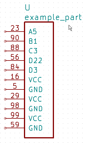
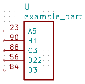
Then the command kipart example.csv -o example1.lib will create a schematic symbol
where the pins are arranged in the order of the rows in the CSV file they are on:
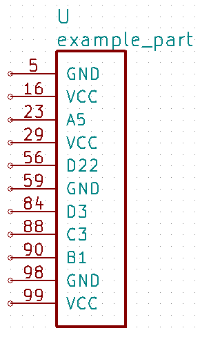
The command kipart -s num example.csv -o example2.lib will create a schematic symbol
where the pins are arranged by their pin numbers:
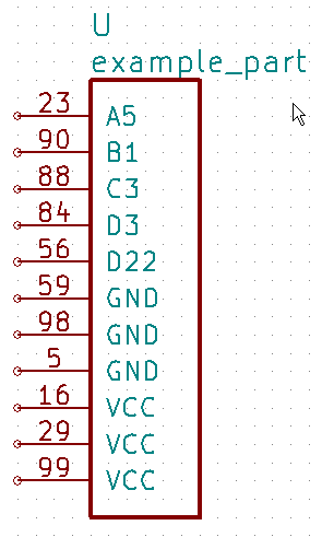
The command kipart -s name example.csv -o example3.lib will create a schematic symbol
where the pins are arranged by their names:
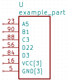
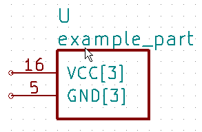
The command kipart -b example.csv -o example4.lib will bundle power and no-connect pins with
identical names (like GND, VCC, and NC) into single pins like so:
Or you could divide the part into two units: one for I/O pins and the other for power pins
by adding a Unit column like this:
example_part

Pin,    Unit,   Type,           Name
23,     IO,     input,          A5
90,     IO,     output,         B1
88,     IO,     bidirectional,  C3
56,     IO,     tristate,       D22
84,     IO,     tristate,       D3
16,     PWR,    power_in,       VCC
5,      PWR,    power_in,       GND
29,     PWR,    power_in,       VCC
98,     PWR,    power_in,       GND
99,     PWR,    power_in,       VCC
59,     PWR,    power_in,       GND
Then the command kipart -b example.csv -o example5.lib results in a part symbol having two separate units:
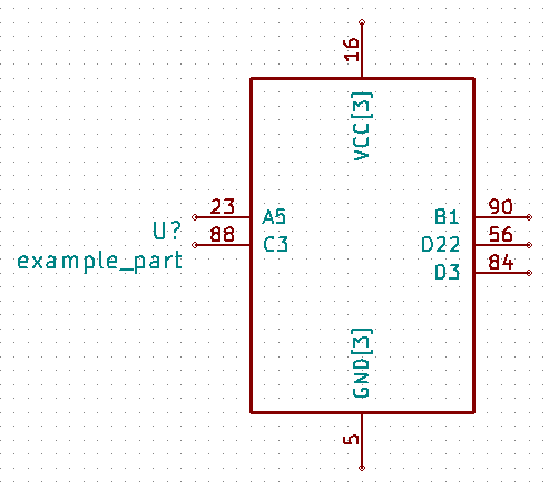
As an alternative, you could go back to a single unit with all the inputs on the left side,
all the outputs on the right side, the VCC pins on the top and the GND pins on the bottom:
example_part

Pin,    Unit,   Type,           Name,   Side
23,     1,      input,          A5,     left
90,     1,      output,         B1,     right
88,     1,      bidirectional,  C3,     left
56,     1,      tristate,       D22,    right
84,     1,      tristate,       D3,     right
16,     1,      power_in,       VCC,    top
5,      1,      power_in,       GND,    bottom
29,     1,      power_in,       VCC,    top
98,     1,      power_in,       GND,    bottom
99,     1,      power_in,       VCC,    top
59,     1,      power_in,       GND,    bottom
Running the command kipart -b example.csv -o example6.lib generates a part symbol with pins on all four sides:
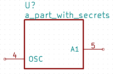
If the input file has a Hidden column, then some, none, or all pins can be made invisible:
a_part_with_secrets

Pin,    Name,   Type,   Side,   Style,      Hidden
1,      N.C.,   in,     left,   clk_low,    Y
2,      GND,    pwr,    left,   ,           yeS
3,      SS_INH, in,     left,   ,           True
4,      OSC,    in,     left,   ,
5,      A1,     out,    right,  ,           False
In the Part Library Editor, hidden pins are grayed out:
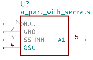
But in Eeschema, they won’t be visible at all:
kilib2csv
Sometimes you have existing libraries that you want to manage with a spreadsheet instead of the KiCad symbol editor. The kilib2csv utility takes one or more library files and converts them into a CSV file. Then the CSV file can be manipulated with a spreadsheet and used as input to KiPart. (Note that any stylized part symbol graphics will be lost in the conversion. KiPart only supports boring, box-like part symbols.)
usage: kilib2csv-script.py [-h] [-v] [-o [file.csv]] [-a] [-w]
                           file.lib [file.lib ...]

Convert a KiCad schematic symbol library file into a CSV file for KiPart.

positional arguments:
  file.lib              KiCad schematic symbol library.

optional arguments:
  -h, --help            show this help message and exit
  -v, --version         show program's version number and exit
  -o [file.csv], --output [file.csv]
                        CSV file created from schematic library file.
  -a, --append          Append to an existing CSV file.
  -w, --overwrite       Allow overwriting of an existing CSV file.
The utility is easy to use:
kilib2csv my_lib1.lib my_lib2.lib -o my_library.csv
Then you can generate a consistent library from the CSV file:
kipart my_library.csv -o my_library_new.lib